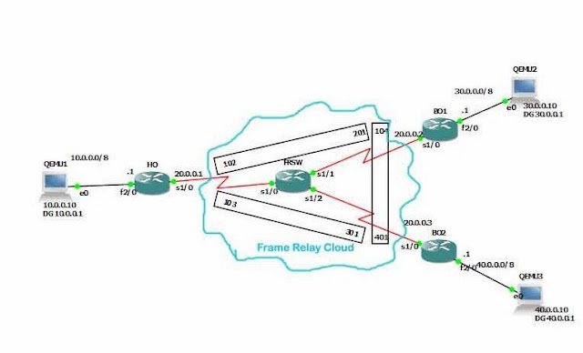
In this post we are going to see how to configure Frame Relay Multi Point Fully Mesh topology using cisco router as frame relay switch in GNS3.
Step 1:Create topology like this,
Step 2:Configure routers Ho and BO1 and BO2 with configurations given below,
In Rotuer HO global config mode,
HO(config)#interface fastethernet2/0
HO(config-if)#ip address 10.0.0.1 255.0.0.0
HO(config-if)#no shutdown
HO(config-if)#exit
HO(config)#interface serial 1/0
HO(config-if)#ip address 20.0.0.1 255.0.0.0
HO(config-if)#encapsulation frame-relay
HO(config-if)#no shutdown
HO(config-if)#exit
In Router BO1 global config mode,
BO1(config)#interface fastethernet2/0
BO1(config-if)#ip address 30.0.0.1 255.0.0.0
BO1(config-if)#no shutdown
BO1(config-if)#exit
BO1(config)#interface serial 1/0
BO1(config-if)#ip address 20.0.0.2 255.0.0.0
BO1(config-if)#encapsulation frame-relay
BO1(config-if)#no shutdown
BO1(config-if)#exit
In Router BO2 global config mode,
BO2(config)#interface fastethernet2/0
BO2(config-if)#ip address 40.0.0.1 255.0.0.0
BO2(config-if)#no shutdown
BO2(config-if)#exit
BO2(config)#interface serial 1/0
BO2(config-if)#ip address 20.0.0.3 255.0.0.0
BO2(config-if)#encapsulation frame-relay
BO2(config-if)#no shutdown
BO2(config-if)#exit
Step 3:Configure host Qemu1,Qemu2 and Qemu3 with appropriate ip address and default gateway
Qemu1 Configuration,
tc@box:~$
tc@box:~$ sudo su
root@box:~#ifconfig eth0 10.0.0.10 netmask 255.0.0.0 up
root@box:~#route add ip default gw 10.0.0.1
root@box:~#route add default gw 10.0.0.1
Qemu2 Configuration,
tc@box:~$
tc@box:~$ sudo su
root@box:~#ifconfig eth0 30.0.0.10 netmask 255.0.0.0 up
root@box:~#route add ip default gw 30.0.0.1
root@box:~#route add default gw 30.0.0.1
Qemu3 Confguration,
tc@box:~$
tc@box:~$ sudo su
root@box:~#ifconfig eth0 40.0.0.10 netmask 255.0.0.0 up
root@box:~#route add ip default gw 40.0.0.1
root@box:~#route add default gw 40.0.0.1
Step 4:Enable Frame Relay in Router FRSW,Command to Enable Frame Relay in Router is
FRSW(config)#frame-relay switching
Step 5:Now configure the interface serial1/0,serial 1/1 and Serial 1/2 with this command to configure PVC between HO to BO1 and HO to BO2,
In FRSW global Config mode,
FRSW(config)#interface serial 1/0
FRSW(config-if)#encapsulation frame-relay
FRSW(config-if)#frame-relay intf-type dce
FRSW(config-if)#frame-relay route 102 interface serial 1/1 201
FRSW(config-if)#frame-relay route 103 interface serial 1/2 301
FRSW(config-if)#no shutdown
FRSW(config-if)#exit
FRSW(config)#interface serial 1/1
FRSW(config-if)#encapsulation frame-relay
FRSW(config-if)#frame-relay intf-type dce
FRSW(config-if)#frame-relay route 201 interface serial 1/0 102
FRSW(config-if)#frame-relay route 104 interface serial 1/2 401
FRSW(config-if)#no shutdown
FRSW(config-if)#exit
FRSW(config)#interface serial 1/2
FRSW(config-if)#encapsulation frame-relay
FRSW(config-if)#frame-relay intf-type dce
FRSW(config-if)#frame-relay route 301 interface serial 1/0 103
FRSW(config-if)#frame-relay route 401 interface serial 1/1 104
FRSW(config-if)#no shutdown
FRSW(config-if)#exit
Step 6:Now configure static route all routers like below,
In Router HO,
HO(config)#ip route 30.0.0.0 255.0.0.0 20.0.0.2
HO(config)#ip route 40.0.0.0 255.0.0.0 20.0.0.3
In Router BO1,
BO1(config)#ip route 10.0.0.0 255.0.0.0 20.0.0.1
BO1(config)#ip route 40.0.0.0 255.0.0.0 20.0.0.3
In Router BO2,
BO2(config)#ip route 10.0.0.0 255.0.0.0 20.0.0.1
BO2(config)#ip route 30.0.0.0 255.0.0.0 20.0.0.2
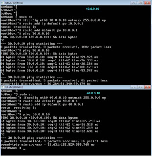
Step 7:Now go to the host in network 10.0.0.0 and ping 30.0.0.10 and then 40.0.0.10->ping 30.0.010
ping 30.0.0.10
Ping both from 10.0.0.10 and 40.0.0.10

Troubleshooting commands,
HO#show frame-relay map
Serial1/0 (up): ip 20.0.0.2 dlci 102(0x66,0x1860), dynamic,
broadcast,, status defined, active
Serial1/0 (up): ip 20.0.0.3 dlci 103(0x67,0x1870), dynamic,
broadcast,, status defined, active
HO#show frame-relay pvc
PVC Statistics for interface Serial1/0 (Frame Relay DTE)
Active Inactive Deleted Static
Local 2 0 0 0
Switched 0 0 0 0
Unused 0 0 0 0
DLCI = 102, DLCI USAGE = LOCAL, PVC STATUS = ACTIVE, INTERFACE = Serial1/0
input pkts 11 output pkts 13 in bytes 1074
out bytes 1168 dropped pkts 0 in pkts dropped 0
out pkts dropped 0 out bytes dropped 0
in FECN pkts 0 in BECN pkts 0 out FECN pkts 0
out BECN pkts 0 in DE pkts 0 out DE pkts 0
out bcast pkts 2 out bcast bytes 68
5 minute input rate 0 bits/sec, 0 packets/sec
5 minute output rate 0 bits/sec, 0 packets/sec
pvc create time 00:11:12, last time pvc status changed 00:10:12
DLCI = 103, DLCI USAGE = LOCAL, PVC STATUS = ACTIVE, INTERFACE = Serial1/0
input pkts 6 output pkts 6 in bytes 554
out bytes 554 dropped pkts 0 in pkts dropped 0
out pkts dropped 0 out bytes dropped 0
in FECN pkts 0 in BECN pkts 0 out FECN pkts 0
out BECN pkts 0 in DE pkts 0 out DE pkts 0
out bcast pkts 1 out bcast bytes 34
5 minute input rate 0 bits/sec, 0 packets/sec
5 minute output rate 0 bits/sec, 0 packets/sec
pvc create time 00:11:14, last time pvc status changed 00:09:35
HO#show frame-relay lmi
LMI Statistics for interface Serial1/0 (Frame Relay DTE) LMI TYPE = CISCO
Invalid Unnumbered info 0 Invalid Prot Disc 0
Invalid dummy Call Ref 0 Invalid Msg Type 0
Invalid Status Message 0 Invalid Lock Shift 0
Invalid Information ID 0 Invalid Report IE Len 0
Invalid Report Request 0 Invalid Keep IE Len 0
Num Status Enq. Sent 105 Num Status msgs Rcvd 77
Num Update Status Rcvd 0 Num Status Timeouts 28
HO#debug frame-relay lmi
HO#debug frame-relay packet
HO#debug frame-relay
In FRSW,
FRSW#show frame-relay route
Input Intf Input Dlci Output Intf Output Dlci Status
Serial1/0 102 Serial1/1 201 active
Serial1/0 103 Serial1/2 301 active
Serial1/1 104 Serial1/2 401 active
Serial1/1 201 Serial1/0 102 active
Serial1/2 301 Serial1/0 103 active
Serial1/2 401 Serial1/1 104 active
In BO2,
BO2#show frame-relay map
Serial1/0 (up): ip 20.0.0.1 dlci 301(0x12D,0x48D0), dynamic,
broadcast,, status defined, active
Serial1/0 (up): ip 20.0.0.2 dlci 401(0x191,0x6410), dynamic,
broadcast,, status defined, active
Step 1:Create topology like this,
Step 2:Configure routers Ho and BO1 and BO2 with configurations given below,
In Rotuer HO global config mode,
HO(config)#interface fastethernet2/0
HO(config-if)#ip address 10.0.0.1 255.0.0.0
HO(config-if)#no shutdown
HO(config-if)#exit
HO(config)#interface serial 1/0
HO(config-if)#ip address 20.0.0.1 255.0.0.0
HO(config-if)#encapsulation frame-relay
HO(config-if)#no shutdown
HO(config-if)#exit
In Router BO1 global config mode,
BO1(config)#interface fastethernet2/0
BO1(config-if)#ip address 30.0.0.1 255.0.0.0
BO1(config-if)#no shutdown
BO1(config-if)#exit
BO1(config)#interface serial 1/0
BO1(config-if)#ip address 20.0.0.2 255.0.0.0
BO1(config-if)#encapsulation frame-relay
BO1(config-if)#no shutdown
BO1(config-if)#exit
In Router BO2 global config mode,
BO2(config)#interface fastethernet2/0
BO2(config-if)#ip address 40.0.0.1 255.0.0.0
BO2(config-if)#no shutdown
BO2(config-if)#exit
BO2(config)#interface serial 1/0
BO2(config-if)#ip address 20.0.0.3 255.0.0.0
BO2(config-if)#encapsulation frame-relay
BO2(config-if)#no shutdown
BO2(config-if)#exit
Step 3:Configure host Qemu1,Qemu2 and Qemu3 with appropriate ip address and default gateway
Qemu1 Configuration,
tc@box:~$
tc@box:~$ sudo su
root@box:~#ifconfig eth0 10.0.0.10 netmask 255.0.0.0 up
root@box:~#route add ip default gw 10.0.0.1
root@box:~#route add default gw 10.0.0.1
Qemu2 Configuration,
tc@box:~$
tc@box:~$ sudo su
root@box:~#ifconfig eth0 30.0.0.10 netmask 255.0.0.0 up
root@box:~#route add ip default gw 30.0.0.1
root@box:~#route add default gw 30.0.0.1
Qemu3 Confguration,
tc@box:~$
tc@box:~$ sudo su
root@box:~#ifconfig eth0 40.0.0.10 netmask 255.0.0.0 up
root@box:~#route add ip default gw 40.0.0.1
root@box:~#route add default gw 40.0.0.1
Step 4:Enable Frame Relay in Router FRSW,Command to Enable Frame Relay in Router is
FRSW(config)#frame-relay switching
Step 5:Now configure the interface serial1/0,serial 1/1 and Serial 1/2 with this command to configure PVC between HO to BO1 and HO to BO2,
In FRSW global Config mode,
FRSW(config)#interface serial 1/0
FRSW(config-if)#encapsulation frame-relay
FRSW(config-if)#frame-relay intf-type dce
FRSW(config-if)#frame-relay route 102 interface serial 1/1 201
FRSW(config-if)#frame-relay route 103 interface serial 1/2 301
FRSW(config-if)#no shutdown
FRSW(config-if)#exit
FRSW(config)#interface serial 1/1
FRSW(config-if)#encapsulation frame-relay
FRSW(config-if)#frame-relay intf-type dce
FRSW(config-if)#frame-relay route 201 interface serial 1/0 102
FRSW(config-if)#frame-relay route 104 interface serial 1/2 401
FRSW(config-if)#no shutdown
FRSW(config-if)#exit
FRSW(config)#interface serial 1/2
FRSW(config-if)#encapsulation frame-relay
FRSW(config-if)#frame-relay intf-type dce
FRSW(config-if)#frame-relay route 301 interface serial 1/0 103
FRSW(config-if)#frame-relay route 401 interface serial 1/1 104
FRSW(config-if)#no shutdown
FRSW(config-if)#exit
Step 6:Now configure static route all routers like below,
In Router HO,
HO(config)#ip route 30.0.0.0 255.0.0.0 20.0.0.2
HO(config)#ip route 40.0.0.0 255.0.0.0 20.0.0.3
In Router BO1,
BO1(config)#ip route 10.0.0.0 255.0.0.0 20.0.0.1
BO1(config)#ip route 40.0.0.0 255.0.0.0 20.0.0.3
In Router BO2,
BO2(config)#ip route 10.0.0.0 255.0.0.0 20.0.0.1
BO2(config)#ip route 30.0.0.0 255.0.0.0 20.0.0.2
Step 7:Now go to the host in network 10.0.0.0 and ping 30.0.0.10 and then 40.0.0.10->ping 30.0.010
ping 30.0.0.10
Ping both from 10.0.0.10 and 40.0.0.10

Troubleshooting commands,
HO#show frame-relay map
Serial1/0 (up): ip 20.0.0.2 dlci 102(0x66,0x1860), dynamic,
broadcast,, status defined, active
Serial1/0 (up): ip 20.0.0.3 dlci 103(0x67,0x1870), dynamic,
broadcast,, status defined, active
HO#show frame-relay pvc
PVC Statistics for interface Serial1/0 (Frame Relay DTE)
Active Inactive Deleted Static
Local 2 0 0 0
Switched 0 0 0 0
Unused 0 0 0 0
DLCI = 102, DLCI USAGE = LOCAL, PVC STATUS = ACTIVE, INTERFACE = Serial1/0
input pkts 11 output pkts 13 in bytes 1074
out bytes 1168 dropped pkts 0 in pkts dropped 0
out pkts dropped 0 out bytes dropped 0
in FECN pkts 0 in BECN pkts 0 out FECN pkts 0
out BECN pkts 0 in DE pkts 0 out DE pkts 0
out bcast pkts 2 out bcast bytes 68
5 minute input rate 0 bits/sec, 0 packets/sec
5 minute output rate 0 bits/sec, 0 packets/sec
pvc create time 00:11:12, last time pvc status changed 00:10:12
DLCI = 103, DLCI USAGE = LOCAL, PVC STATUS = ACTIVE, INTERFACE = Serial1/0
input pkts 6 output pkts 6 in bytes 554
out bytes 554 dropped pkts 0 in pkts dropped 0
out pkts dropped 0 out bytes dropped 0
in FECN pkts 0 in BECN pkts 0 out FECN pkts 0
out BECN pkts 0 in DE pkts 0 out DE pkts 0
out bcast pkts 1 out bcast bytes 34
5 minute input rate 0 bits/sec, 0 packets/sec
5 minute output rate 0 bits/sec, 0 packets/sec
pvc create time 00:11:14, last time pvc status changed 00:09:35
HO#show frame-relay lmi
LMI Statistics for interface Serial1/0 (Frame Relay DTE) LMI TYPE = CISCO
Invalid Unnumbered info 0 Invalid Prot Disc 0
Invalid dummy Call Ref 0 Invalid Msg Type 0
Invalid Status Message 0 Invalid Lock Shift 0
Invalid Information ID 0 Invalid Report IE Len 0
Invalid Report Request 0 Invalid Keep IE Len 0
Num Status Enq. Sent 105 Num Status msgs Rcvd 77
Num Update Status Rcvd 0 Num Status Timeouts 28
HO#debug frame-relay lmi
HO#debug frame-relay packet
HO#debug frame-relay
In FRSW,
FRSW#show frame-relay route
Input Intf Input Dlci Output Intf Output Dlci Status
Serial1/0 102 Serial1/1 201 active
Serial1/0 103 Serial1/2 301 active
Serial1/1 104 Serial1/2 401 active
Serial1/1 201 Serial1/0 102 active
Serial1/2 301 Serial1/0 103 active
Serial1/2 401 Serial1/1 104 active
In BO2,
BO2#show frame-relay map
Serial1/0 (up): ip 20.0.0.1 dlci 301(0x12D,0x48D0), dynamic,
broadcast,, status defined, active
Serial1/0 (up): ip 20.0.0.2 dlci 401(0x191,0x6410), dynamic,
broadcast,, status defined, active

Post a Comment