How to Configure Inter-VLAN Routing or Route On a Stick Using Cisco Packet Tracer and Communication between different VLAN's in a network with layer 2 switches and trunk configuration.
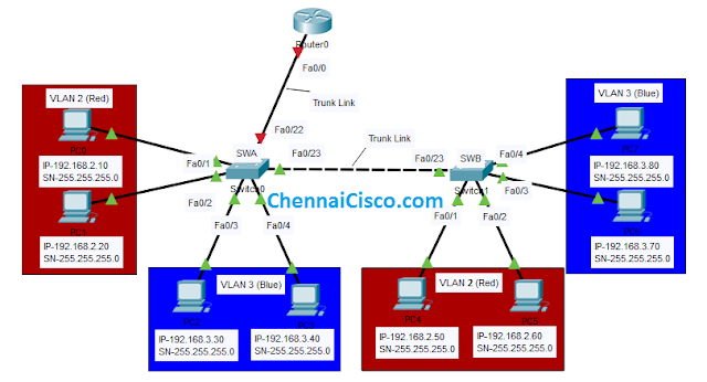
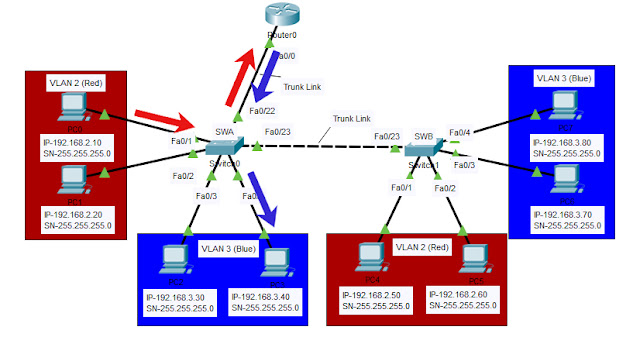
Create a topology like given in below image,
In above topology, host PC0 and PC1 configured to VLAN2, host PC2,PC3,PC6 and PC7 configured to VLAN3, host PC4 and PC5 configured to VLAN 4.
SWA Fa0/1(PC0)-->VLAN 2 name Red
SWA Fa0/2(PC1)-->VLAN 2 name Red
SWA Fa0/3(PC2)-->VLAN 3 name Blue
SWA Fa0/4(PC3)-->VLAN 3 name Blue
SWB Fa0/1(PC4)-->VLAN 2 name Red
SWB Fa0/2(PC5)-->VLAN 2 name Red
SWB Fa0/3(PC6)-->VLAN 3 name Blue
SWB Fa0/4(PC7)-->VLAN 3 name Blue
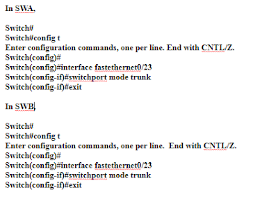
Link connecting SWA Fa0/23 and SWB Fa0/23 configured as Trunk.Configuring VLAN and Trunk already seen in previous post.
Without Inter-VLAN routing, host in same VLAN can communicate,host in different VLAN can't communicate with each other.Link connecting two switches configured as Trunk, So,the host in VLAN3 in SWA can communicate with host in VLAN 3 SWB.What if we need to make host communicate between different VLAN's, we need layer 3 device to make this happen like router or layer 3 switch.
VLAN Cofiguration
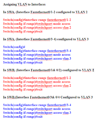
Assigning Ports to VLAN
Above command is to configure range of interfaces to a VLAN.Command to configure each interface interface individually to a vlan is given below,
Example:To configure interface individually.
SWA(config)#interface fastethernet0/1
SWA(config-if-range)#switchport mode access
SWA(config-if-range)#switchport access vlan 2
SWA(config-if-range)#exit
Trunk Configuration
Before Inter-VLAN Routing configuration,I am going to check by pinging host in different VLAN with above configuraiton only.We see how it works,
Ping IP-192.168.3.40,192.168.2.60, 192.168.3.80 From host PC3(192.168.2.10).
Above results shows that, Only host in same VLAN communicates successfully,Here, Source is 192.168.2.10 belongs to VLAN 2.we got reply from host that is in VLAN 2 only.
Here, Router is connected to a switch SWA to attain Inter-VLAN Routing.For that, we have to configure the link connecting router and switch as trunk link.so,the packets from different VLAN can be forwaded through this link.Then, we have to create sub interfaces in a router for each network and configure subinterfaces with IP address, that is going to be act as default gateway for each network.
- Configure link between Router and Switch as trunk.
- Create sub-interfaces and configure IP.
- Configure sub-interfaces with encapsulation 802.1q
In SWA Global Configuraion mode,
SWA(config)#interface fastethernet0/22
SWA(config-if)#switchport mode trunk
SWA(config-if)#exit
Creating sub-interfaces and IP address in router.
Router(config)#interface fastethernet0/0
Router(config-if)#no shutdown
Router(config-if)#exit
Router(config)#interface fastethernet0/0.1
Router(config-subif)#encapsulation dot1q 2
Router(config-subif)#ip address 192.168.2.1 255.255.255.0
Router(config-subif)#
Router(config)#interface fastethernet0/0.2
Router(config-subif)#encapsulation dot1q 3
Router(config-subif)#ip address 192.168.3.1 255.255.255.0
Router(config-subif)#exit
After Inter-VLAN configuration just ping and check same host as we pinged before Inter-VLAN Configuration.
All host communicated sucessfully after Inter-vlan configuration,network administrator can manually give an access to user from one vlan to another vlan or restrict the user based on our requirements.Here, different vlan communicates with help of layer 3 router.
If above image is not clear Download the High Resolution Pic Download Link
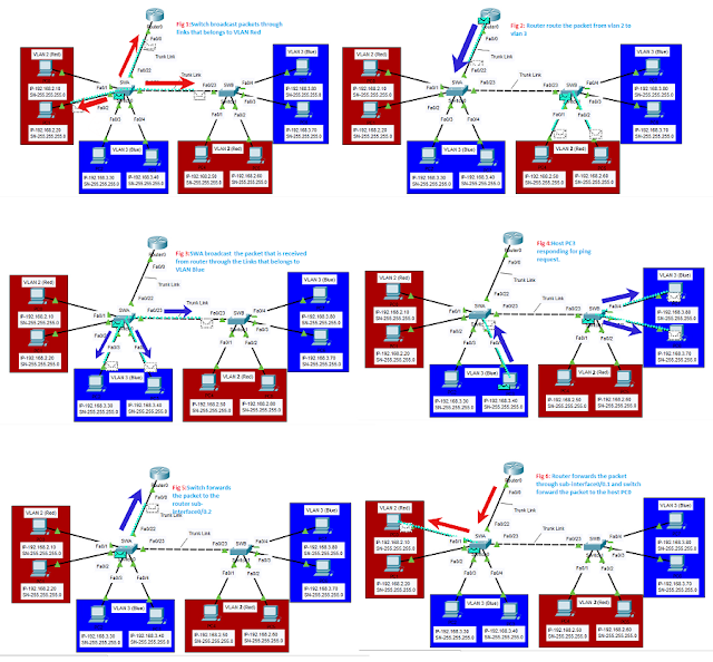
This image shows ICMP packet activity in this network, after pinging from one host to another host in different VLAN with Inter VLAN Routing configuration.
After pinging the IP 192.168.3.40 of Vlan3 (Blue) from host 192.168.2.10 of vlan2 (Red).ICMP packets forwarded to layer 2 switch SWA through fastethernet 0/1.shown in Figure 1 in above image..
After receiving packets switch broadcast to all interfaces that is part of vlan2 ,here the packet broadcasted through interface fastethernet 0/2,interface fastethernet 0/23 is a trunk link between SWA and SWB,interface fastethernet 0/22 is a trunk link connected to a router.Packet not forwarded to vlan blue.Refer Fig 2.
Host PC1,PC4 and PC5 will drop the packets,Only router will forward the vlan2 packets through sub-interface that belongs vlan3 (blue).Here, interface fastethernet 0/0 of Router is configured with sub-interfaces, interface fastethernet 0/0.1 with IP address 192.168.2.1 it will act as a default gateway for red vlan.Interface fastethernet 0/0.2 is configured with IP address 192.168.3.1 this act as a default gateway for vlan blue.So, the packet received through sub-Interface belongs to vlan red, that is fastethernet 0/0.1 routed to sub-interface fastethernet 0/0.2 that belongs to vlan 3.Packet received as vlan2 red, goes out as vlan3 blue packet.
Switch gets the packet from router and Switch SWA forwards the received packets from the router through ports that is belongs to vlan3 blue only,Fastethernet0/3,Fastethernet0/4 and Fastethernet0/23.Host PC2,PC3 and SWB receives the packet.SWB forwards the packet to host PC6 and PC7,both host will check destination IP address and they drops the packet.Only host PC3 with IP address of 192.168.3.40 will reply all other host in blue vlan drops the packet.Ref Fig.3&4.
Host PC3 responding to the request and SWA forwards the packet to the default gateway,Packet received through sub-interface fastethernet0/0.2 IP address 192.168.3.1 belongs to vlan3.Rotuer forwards the packet through sub-interface fastethernet0/0.1 to switch SWA,Switch sends the packet to the host PC0 192.168.2.10.This is the complete process going on for Ping in this Inter-vlan topology.
If ARP table already has a MAC address of destination then the packet sends to a default gateway without broadcast and router forwards through sub-interface of destination host vlan(VLAN3 in above example).Then Destination host sends reply packet to the default gateway,router forward the packet through the particular sub-interface that act as default gateway for particular vlan(VLAN2 in this example).Ref Above image.
You May Interested in:
VLAN Configuration in Packet Tracer
VLAN Configuration in Multiple Switches



This is a very interesting post. Your information is very important to me. Thanks for sharing.Segment routing
ReplyDeleteSuperb blog. When I saw Jon’s email, I know the post will be good and I am surprised that you wrote it man!
ReplyDeleteWe are the best Share Market training academy in Chennai, offering best stock market trading and technical analysis training online & live classes. Enroll now for share market classes by today.for more details contact us: +91 95858 44338, +91 95669 7779