Understanding Spanning Tree Protocol (STP) in Packet Tracer with Simple topology using 2950-24 Switch.
Spanning Tree Protocol (STP) presents in layer 2 Switches and Bridges to keep the network loop free,Its IEEE Standard is IEEE 802.1D. Redundant links between layer 2 devices are very important in the network,it prevents total network failure.Single link between devices fails, there will be network failure. So, multiple links are very important.At the same time multiple links often cause many problems in the network, Switches forwards and receives same frames again and again in a looped network and it will take entire bandwidth and it makes the network unstable, and there will be a problem in maintaing stable MAC address table.STP is uses Spanning Tree Algorithm (SPA) to construct the loop free network.
Default Spanning Tree Timers
Blocked Port (Loss of BPDU) Max Age = 20 secBy deafault, All the ports are in blocking state when the switch starts,Blocking ports just listen to Bridge Protocol Data Units (BPDU).Looped path will be in blocking state, if any links fails the STP recalculate the paths.
Listening Port (Forward Delay = 15 sec)
Listening port will listen to Bridge Protocol Data Units (BPDU) to make sure there is no loops in the network.Listenting port prepares frames to foward but it won't populate the MAC address table.
Learning Port (Forward Delay = 15 sec)
Learning port learns all path in a Switched network by using received Bridge Protocol Data Units (BPDU).Learning state generates the MAC address table, but it won't forward the data frames.
Forwarding Port
Forwarding port sends and receives all the data frames.Forwarding port will be either designated or Root port.
Disabled Port
Disabled port is administratively disabled, it won't participate in this process,
Terms Using by Spanning Tree Protocol
BPDU : Bridge Protocol Data Units contains the information of the Switches to use in the root switch selection process.When switch starts the spanning tree is used to find the root switch.BPDU will be sent to all devices in network with BID.Bridge ID BID : STP tracks all switches in switched network. Bridge ID is the combination of Bridge Priority(32768) and Switch base MAC address.By default 32768 is the priority in all cisco Switches.
Designated Port: Designated port of the switch will be in the forwarding state.All ports of the Root Switch will be designated port.
Non designated Port: Non Designated port will be in blocking to avoid loop.This port cost will be higher than the designated port.One or more port in Non root bridge will be in blocking state to avoid looped path.
Root Bridge : Switch with lowest BridgeID(BID) will become the root bridge.
Non root Bridge : Other than Root bridge with higher cost will becomes non root bridge.
Forwarding Port: Forwarding port will be either designated port or Root port.
Blocked Port: Blocket port will not forward the frames.
Port cost based on Link speed IEEE Specification
Link speed Link Cost (IEEE)
10 Gbps - 2
1 Gbps- 4
100 Mbps -19
10 Mbps -100
Spanning Tree Timers
Hello: By default hello time between each BPDU is 2 secs.We can set hello time between 1 to 10 secondsForward Delay: Time spent in the lestening and learning state.By default, it is 15 sec. We can set this time between 4 to 30 seconds.
Max age: Maximum length of time that waits before a bridge port saves received BPDU Information.
We are going to see how Spannig Tree Protocol (STP) works on this this simple packet tracer topology.
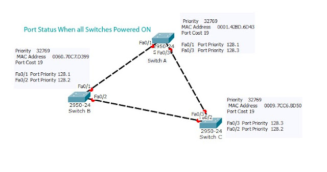
In this topology, we are using three switches Switch A, Switch B and Switch C. I have chosen 2950-24 switch in packet tracer.when we place switch in working space switch will turn on in packet tracer and STP starts running once the switch is ON by default,then STP will choose Root Bridge and block looped paths.
Choosing Root Bridge
When switches powered ON, all the switches in network decides themselves as a root switch and sends BPDU to other neighbour switches.After receiving Bridge Protocol Data Unit (BPDU) that contains Bridge ID with the information of switch priority (32768) by default and Base MAC address of Switch, The Switch will select root bridge by choosing switch with lowest priority value. If all switches have same priority then switch with lowest MAC address will be chosen as Root Switch.
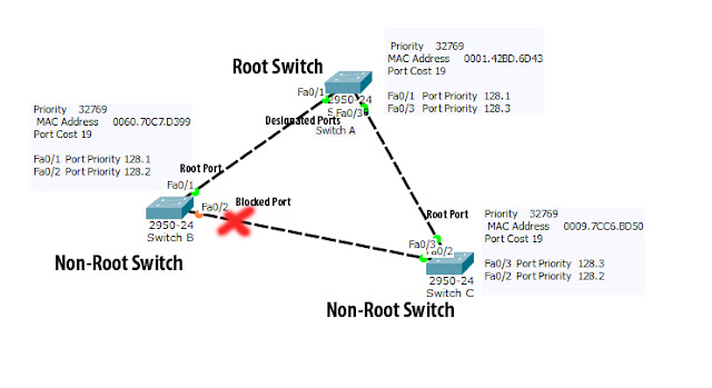
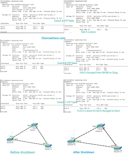
In this, topology all switches have same bridge priority, So Spanning Tree Protocol will check for the MAC address in received BPDU. Here Switch A has the lowest MAC so Switch A becomes root switch, switch B and Switch C are Non-Root switches.
All ports of root switch become designated ports(forwarding Port), the best port that connects Non-Root Switch to the Root switch becomes root port.Here Switch A Port Fa0/1 and Fa0/3 becomes designated Ports.Switch B fa0/1 and Switch C fa0/3 becomes root port.Check above Image
But there is another link connects switch B and Switch C that Creates loop.So Spanning tree will block one of the port in this switches.Either Fa0/2 Port of Switch B or Fa0/2 port of Switch C.
Here two switches are directly connected to the root switch,so The port of the switch with highest bridge ID will be blocked, spanning tree choose designated port from the switch with lowest bridge ID.Here Switch B has higher Bridge ID value than Switch C. So, Fa0/2 of switch C becomes designated port and Fa0/2 port of Switch B will be made as Blocking port (Alternate port).Check above image.
Let's See what happens when we shutdown one of the links in this topology.
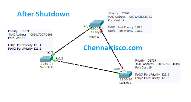
If any link fails the spanning tree will re calculate the path.Here consider the link between switch A and Switch B fails.For that a im going to shutdown the port of switch C fa0/3 by giving command in global configuration mode in Swich C.Switch(config)#
Switch(config)#int fa0/3
Switch(config-if)#shutdown
Then the link between switch B and Switch c become active.Switch B fa0/2 port becomes designated port from blocking port,even though it has higher Bridge ID value than Switch C.Because Only Switch B connects to root Switch, So port fa0/3 becomes designated and port fa0/3 changes to root port.
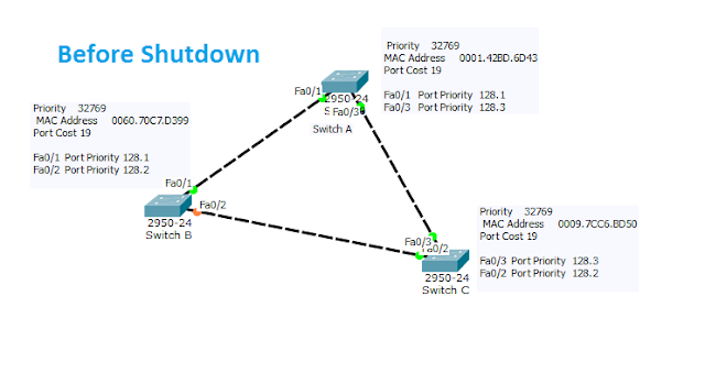
Spanning Tree Table comparison Before and After Shutdown.
How Spanning Tree Protocol (STP) works in Packet Tracer Topology Full Video
How Spanning Tree Protocol (STP) works in Packet Tracer Topology Full Video
Post a Comment