How to Configure VLAN in Cisco Switch Using Packet Tracer Simulator with a Simple Topology Example.
VLAN- Virtual Local Area Network
- VLAN is Virtually grouping of host for Various Purpose.
- VLAN reduces the size the of broadcast and collision domain within a layer 2 switched network.
- Broadcast frames from one VLAN will not be forwarded to another VLAN.
- Logically grouping of host can be done by physical port association.Host from one VLAN cannot communicate with host from another VLAN.It reduces unwanted broadcast traffic in a network.
- We can isolate users based on workgroup or users performs similar functions in VLAN.By this we can redcuce unwanted network traffic forwarding to users who is doing different functions.
- Layer 2 switching and Layer 3 routing are used to reduce the size of collision and Broadcast domains.
- VLAN Provides security by isolating users.Group of users needed high security can be grouped into a seperate VLAN,So, Other users in a network cannot communicate with this users.
- Communication between VLAN happens only by using router.It is called as inter VLAN routing.
- We need routers to break larger broadcast domain into smaller one,but VLAN do this in Layer 2 Switched network.
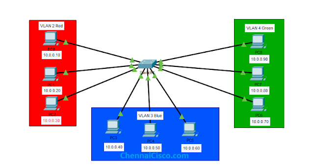
Step:1 Create a topology like in below image,
Note:- Here all VLAN host were configured with IP in Same network to make you understand VLAN in better way. In realtime, we have to use different network for each VLAN to achieve Inter VLAN routing. It can be classful network or subnetted network based on our requirement.
Step:2 Configure IP address to all PC.
VLAN not configured in above topology and all PC's are configured with IP address in a same network 10.0.0.0 and subnet mask 255.0.0.0. Switch 2950-24 used in this topology.
PC0 is Connected to Fastethernet0/1,IP address 10.0.0.10
PC1 is Connected to Fastethernet0/2,IP address 10.0.0.20
PC2 is Connected to Fastethernet0/3,IP address 10.0.0.30
PC3 is Connected to Fastethernet0/4,IP address 10.0.0.40
PC4 is Connected to Fastethernet0/5,IP address 10.0.0.50
PC5 is Connected to Fastethernet0/6,IP address 10.0.0.60
PC6 is Connected to Fastethernet0/7,IP address 10.0.0.70
PC7 is Connected to Fastethernet0/8,IP address 10.0.0.80
PC8 is Connected to Fastethernet0/9,IP address 10.0.0.90
Step:3 Ping hosts in a network without VLAN configuration.
Only IP address are configured to PC's,VLAN not configured.Now I am going to ping host 10.0.0.30,10.0.0.60,10.0.0.90 from 10.0.0.10 to check whether we are getting reply or not.
Click on PC0->Desktop->Command Prompt.Then give this command in that window,
In,PC0
Ping 10.0.0.30
Ping 10.0.0.60
Ping 10.0.0.90
We are getting reply from all host, without any restrictions.
Step:4 Configure VLAN in a switch 2950-24,
VLAN 2 for interface fastethernet 0/1,0/2,0/3
VLAN 3 for interface fastethernet 0/4,0/5,0/6
VLAN 4 for interface fastethernet 0/7,0/8,0/9
Here 9 host are there, seperated as three groups with three host per group.I am going fastethernet0/1-0/3 to VLAN 2 named as Red, Fastethernet0/4-0/6 to VLAN 3 named as Blue,Fastethernet 0/7-0/9 to VLAN 4 named as Green.Like given in a image below.
To cofigure VLAN in a Switch,Click on Switch, then go to CLI tab on the switch and give this command.
Creating a VLAN and name for the it.
Switch(config)#
Switch(config)#vlan 2
Switch(config-vlan)#name red
Switch(config-vlan)#exit
Switch(config)#vlan 3
Switch(config-vlan)#name blue
Switch(config-vlan)#exit
Switch(config)#vlan 4
Switch(config-vlan)#name green
Switch(config-vlan)#exit
Assigning interfaces with vlan to the range of interfaces.Here, I am going configure Interfaces 1 to 3 to VLAN 2 so , we can specify a range start to end that is going to be configured to a single VLAN.
Switch(config)#interface range fastethernet0/1-3
Switch(config-if-range)#switchport mode access
Switch(config-if-range)#switchport access vlan 2
Switch(config-if-range)#exit
Switch(config)#
Switch(config)#interface range fastethernet0/4-6
Switch(config-if-range)#switchport mode access
Switch(config-if-range)#switchport access vlan 3
Switch(config-if-range)#exit
Switch(config)#
Switch(config)#interface range fastethernet0/7-9
Switch(config-if-range)#switchport mode access
Switch(config-if-range)#switchport access vlan 4
Switch(config-if-range)#exit
Or, we can configure each individual interfaces like this,but it takes time.But, I just showing you how to configure single interfaces in case if you want to do.
Switch(config)#
Switch(config)#interface fastethernet0/1
Switch(config-if-range)#switchport mode access
Switch(config-if-range)#switchport access vlan 2
Switch(config-if-range)#exit
Above command is to configure VLAN to a single interface.
After configuring VLAN and assigning ports to a Vlan,Only host in same Vlan can communicate with each other,Host from different Vlan can't communicate each other.
To check VLAN configuration details, give this command in Privileged Mode.It will give the configured VLAN information in Cisco Switch
Switch#show vlan brief
VLAN Name Status Ports
---- -------------------------------- --------- -------------------------------
1 default active Fa0/10, Fa0/11, Fa0/12, Fa0/13
Fa0/14, Fa0/15, Fa0/16, Fa0/17
Fa0/18, Fa0/19, Fa0/20, Fa0/21
Fa0/22, Fa0/23, Fa0/24
2 red active Fa0/1, Fa0/2, Fa0/3
3 blue active Fa0/4, Fa0/5, Fa0/6
4 green active Fa0/7, Fa0/8, Fa0/9
1002 fddi-default active
1003 token-ring-default active
1004 fddinet-default active
1005 trnet-default active
Switch#
Switch#
A
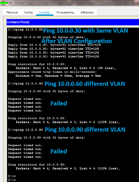
To check, how vlan works based on our configuration in this topology, I am going ping same host that already pinged without VLAN configuration with current configuration.
10.0.0.10 belongs to VLAN 2
10.0.0.30 belongs to VLAN 2
10.0.0.60 belongs to VLAN 3
10.0.0.90 belongs to VLAN 4
Above screen shows that host from same vlan can communicate other host from different Vlan failed to Communicate.In this method we can virtually break the large broadcast domain to smaller one.Most secured host can be assigned to a seperate vlan from others, it will isolate users.
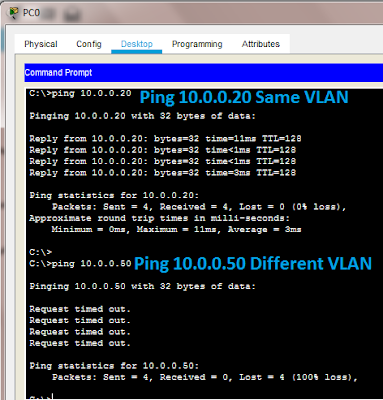
We can ping other host to check how it works, I am going ping 10.0.0.20 and 10.0.0.50 from 10.0.0.10.
Here,
10.0.0.10 belongs to VLAN 2
10.0.0.20 belongs to VLAN 2
10.0.0.50 belongs to VLAN 3
We get reply successfully from the host in same VLAN,Failed in Different VLAN
VLAN Troubleshooting Commands.
Switch#show vlan id 2 (This command will give us information about particular Vlan ID
Here, I am checking the information of VLAN 2)
VLAN Name Status Ports
---- -------------------------------- ---------
2 red active Fa0/1, Fa0/2, Fa0/3
Switch#show vlan brief (This command will give us information about all vlans in the switch.)
Switch#show vlan name blue (This Command Gives information based on Vlan Name)
VLAN Name Status Ports
---- -------------------------------- ---------
2 blue active Fa0/4, Fa0/5, Fa0/6
Switch#show vlan ?
brief VTP all VLAN status in brief
id VTP VLAN status by VLAN id
name VTP VLAN status by VLAN name
- VLAN Configuration in Packet Tracer
- VLAN in Cisco Packet Tracer
- Assigning name for the VLAN
- Configuring VLAN to an interfaces.
- CCNA and CCNP Free Online Course Lab


It was informative. Thanks from Our team
ReplyDelete